There’s more to a
hydraulic power unit than pressure, flow, and valve operation. Safety, maintenance access, component pressure ratings, stored hydraulic energy, hose routing, and site requirements all need to be considered as part of the overall HPU design.
HPU Safety Considerations
It is important to be aware of the hazards associated with HPUs. Generally speaking, the greatest hazards include pressurized hydraulic fluid, stored hydraulic energy, electrical power supply (high voltage, automotive batteries) and exposure to engine exhaust.
HPU safety and serviceability can be improved through additional components and
custom design features beyond the system's basic operating requirements. These additions can increase cost and complexity of the unit, so the final configuration should be based on the assessed risk, site standards, and project requirements.
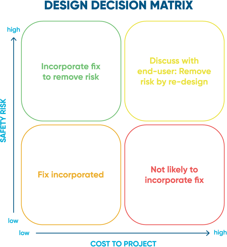
These options can be reviewed with the end user during project development to design a system that balances safety, maintenance requirements, system complexity, and overall cost.
Hydraulic Component Pressure Ratings
It is important to understand both how hydraulic pressure is generated within the HPU and how that pressure is controlled. Many pumps include an internal pressure limit, while most HPU systems also incorporate a separate pressure relief valve, providing two levels of protection against overpressure.
Despite this, the designer must be careful to select fittings and components that are rated for (at least) the maximum pump discharge pressure including any expected system pressure spikes or surges. The pump technology should also be understood to determine whether a failure could result in additional pressure being generated, and how much pressure the pump is ultimately capable of producing.
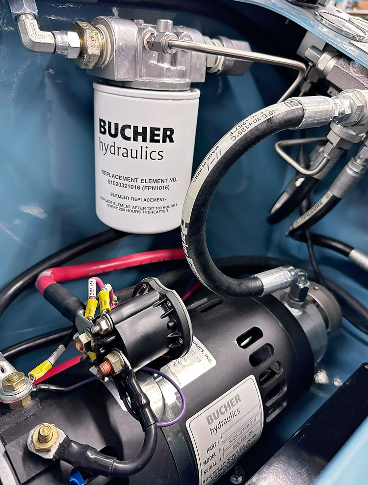
Within the hydraulics industry, all components will have published maximum working pressures and temperature ranges. Each component’s maximum working pressure must meet or exceed the maximum pressure expected within the HPU system.
Most major manufacturers of hydraulic components will state that each component has been tested to burst with 4:1 safety factor. For example, a hose rated to 3,000 psi should withstand at minimum a pressure of 12,000 psi prior to bursting. However, this burst pressure is for testing purposes only and must not be relied upon for system design.
It is important for both the HPU designer and end user to understand the maximum working pressure of each component and how they fit within the operating system. Pressure ratings also need to be reviewed for when
designing HPUs for cold weather, as low temperatures can affect component performance. Depending on the project risk and site specifications, components with additional safety factors may also be selected.
Pressure Lines and Bleed Valves
Double block and bleed valves allow the operator to positively isolate and bleed any residual pressure from the lines prior to removal of the instrument or disconnection of a line. Common locations of double block and bleed valves are between the HPU and valve cylinder or between the pressure source and instrumentation, such as pressure transmitters, switches, and gauges.
Without double block and bleed valves, the discharge of residual hydraulic pressure cannot be controlled, and may result in high pressure oil discharge or leakage putting the operator and surrounding sensitive equipment in danger.
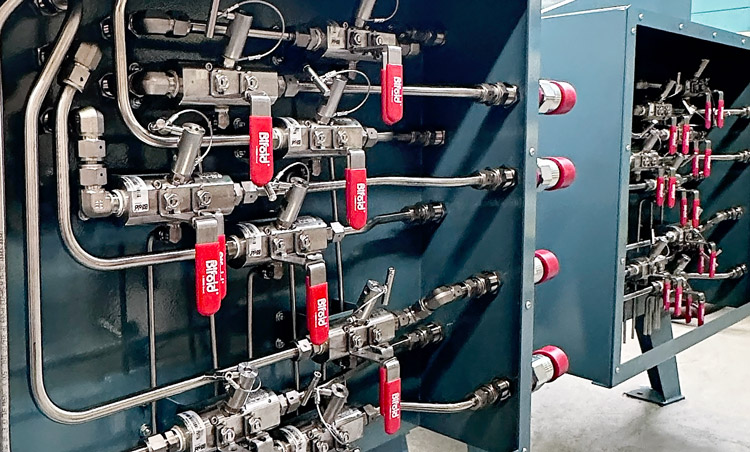
Bleed lines from the double block and bleed can either be directed into a suitable catch-can to monitor oil flow, or collected and routed back to the hydraulic reservoir. When bleeding a system, visual verification of flow rate out of the bleed is critical to ensure a zero energy state. If the lines are return directly to the reservoir, a visual flow meter can be supplied so the operator can verify bleed rate.
Bleeding down hydraulic accumulators requires additional safety considerations, because they store massive amounts of energy, even after the HPU is shut down. It is critical that maintenance personnel are made aware of this danger and are trained on how to safely isolate and depressurize the accumulator before performing maintenance.
Hose Restraints
Hydraulic hose is widely used because it provides a practical, flexible, safe, and cost effective method of transporting pressurized hydraulic fluid. Despite this, there is still a risk that the hose or a crimped fitting connection may fail.
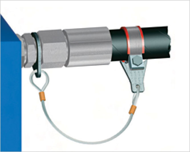
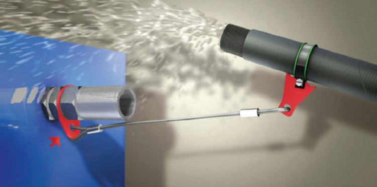
If a pressurized hose separates from a fitting or connection, the loose hose may whip or flail until the system is depressurized, creating a risk of injury. At times, it may be necessary for an operator to be within proximity of, or directly next to pressurized hydraulic hose. To prevent hose whip in the event of a failure, it is recommended that end users specify hose restraints.
Hydraulic Tubing vs. Hose
Despite its widespread use, hydraulic hose has some drawbacks. Hydraulic tubing and fittings may be used in its place (typically stainless steel such as Swagelok or Hylok). Use of hydraulic tubing results in a compact and cleaner looking final product as the operator can easily trace the path of each tube from its respective start and end point.
Hydraulic tubing eliminates the potential for hose whip, however, high-pressure fluid release and fitting failure must still be considered. Tubing can also increase the cost of the HPU due to the additional material and labour required for bending, fitting, and installation.
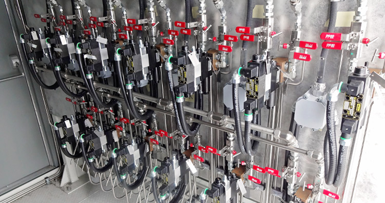
Shown above is a hydraulic directional control valve wall assembled with hydraulic tubing installed within an HPU. The wall is connected to thirteen process on/off valves, each equipped with double block and bleed valves that allow individual control valves to be serviced or replaced without shutting down the entire HPU. Using hydraulic tubing also helps create a more compact installation.
Site Access Considerations
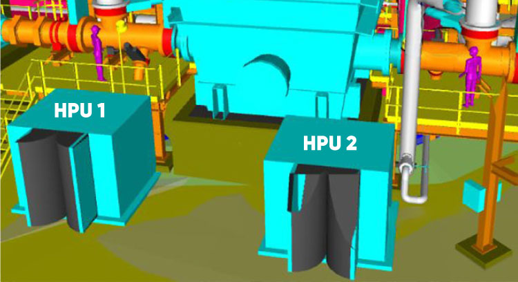
Most plant sites have areas with restricted access to HPUs due to piping, pipe supports, structural members, catwalks, cable trays, equipment, etc. When an HPU is to be installed in such locations, the designer must work with the end-user to review the allowable space, and access points for maintenance, equipment removal and operator access.
HPU Maintenance and Serviceability
When maintenance is required, the HPU may be removed completely and transported to a shop where the necessary tools and space exist to complete the work. How and where maintenance will be performed should be considered during the original HPU design. A planned
HPU preventive maintenance program can also help identify service requirements before major components need to be replaced.
If the HPU is integrated into the plant site or removal is too labour-intensive, maintenance may need to be completed in the field. In these situations, mobile equipment such as a forklift or crane may be required to remove major components.
The plant layout, piping configuration, and available equipment should be reviewed to ensure suitable access for maintenance and service. During the design phase, the HPU designer can provide a preliminary HPU equipment layout showing key access points for review and approval prior to progressing to detailed design.
Designing Safe and Serviceable HPUs for Industrial Sites
HPU design should consider not only the pressure and flow required to operate a valve. Stored-energy hazards, component ratings, hydraulic isolation, hose and tubing configuration, operator access, and future maintenance requirements should all be considered as part of the overall system design..
PEAK Dynamic Systems designs and builds
custom hydraulic power units in Edmonton, Alberta for industrial valve applications throughout Western Canada. HPU layouts can be tailored to site access, maintenance needs, environmental conditions, and safety considerations.


