Hydraulic power units can be built around the specific needs of an industrial valve application. Beyond opening and closing the valve, an HPU can also provide fail-safe positioning, faster valve stroke speeds, stored hydraulic energy, PLC controls, remote operation, and monitoring for pressure, temperature, and oil level.
Fail Position (Fail Open/Fail Closed)
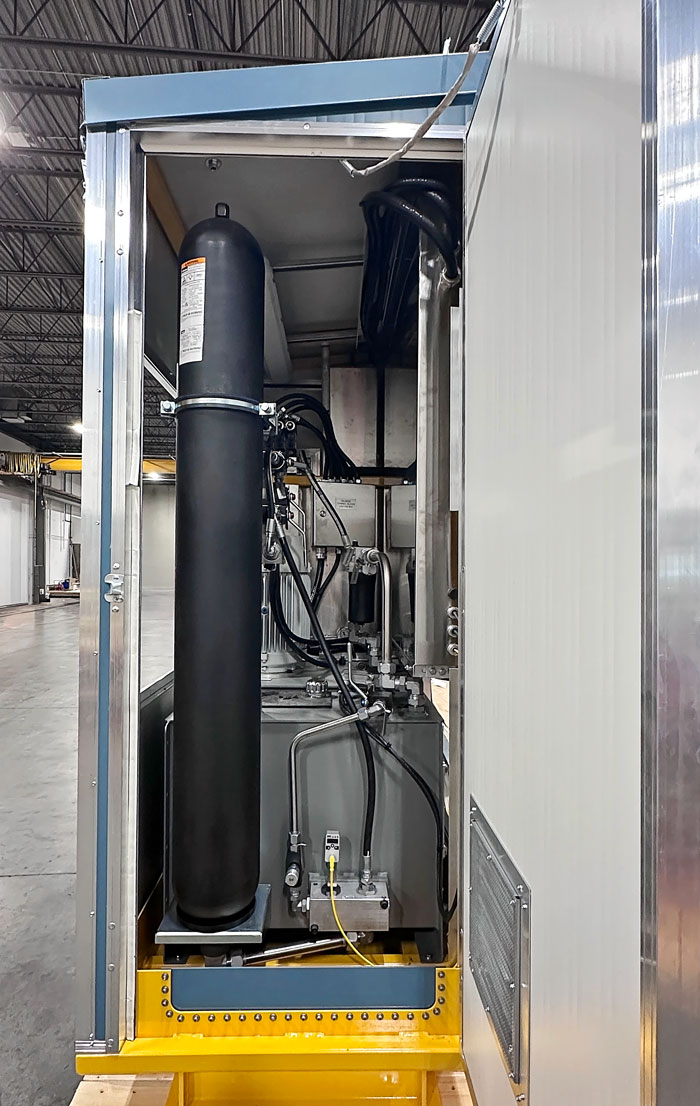
In the event of a loss of power or signal, process or safety requirements may require the valve(s) to be in a fully open or closed position. If electrical power is lost, the electrically driven HPU hydraulic pump is no longer available to generate hydraulic pressure. A hydraulic accumulator can be used to store pressurized hydraulic fluid, providing the energy needed to move the valve to its required fail-safe position.
How Hydraulic Accumulators Provide Fail-Safe Operation
When not called to move a valve open or closed, the hydraulic pump can be used to fill and pressurize a hydraulic accumulator with oil. In the event of an unexpected power loss, a directional control valve can shift to release the stored hydraulic oil required to actuate the valve to a fail-safe position.
Accumulators must be sized considering the volume and pressure required to operate the actuator(s) under fail conditions, the total number of actuators that may need to operate at once, and the number of open/close cycles required after power is lost. Some plant control systems may also require valves to continue operating for a period of time after power failure.
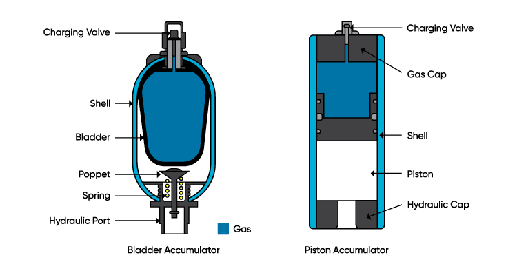
Accumulators play a major role within the HPU and depending on the functional requirements, can occupy a significant amount of space. There two common accumulator designs: bladder and piston.
Bladder Accumulators
Bladder style accumulators are generally used when the required volume of pressurized oil is relatively low, such as when the HPU operates a small number of process valves during a power or signal failure.
Bladder accumulators are available in capacities up to approximately 15 gallons. If more oil storage is needed, multiple accumulators can be connected together to provide the required volume.
This presents an increased risk to operations due to the additional connections and fittings required (and potential leak points). As well, each accumulator needs to be isolated for bleed down and testing which adds time to routine maintenance.
Piston Accumulators
Piston style accumulators are commonly available in sizes up to 50 gallons, with up to 250 gallons of capacity in rare cases. Because these larger capacity accumulators increase in height rather than footprint, multiple units can be installed side by side while taking up less floor space than multiple bladder accumulators.
Additionally, as piston accumulators separate high pressure nitrogen from high pressure oil via a piston seal. As the piston seal wears, performance declines gradually and noticeably over time. In comparison, bladder accumulators may fail instantly with no prior deterioration in performance. For this reason, piston accumulators allow the HPU to continue operation until maintenance can be scheduled.
Configuring an HPU for Fail-Last Position
Process or safety requirements may also require the valve(s) to hold their last position in the event of power or signal loss. During normal operation, a directional control valve directs pressurized oil to one side of the hydraulic cylinder or the other to open or close the valve. When the directional control valve deactivates, it returns to a neutral position where pressurized oil is not directed to any port (no oil movement). The directional control valve will also return to the neutral position when called to fail in position.
When there is no oil movement, the HPU pump will either turn off via pressure control, compensate to no flow, or recirculate the oil back to the hydraulic tank through a pressure relief valve. Recirculation generally occurs only on
portable HPUs (diesel/gasoline or electric). In these systems, the operator should shut down the HPU once valve operation is complete to avoid unnecessary pump operation and excess heat buildup in the hydraulic oil.
The pressurized hydraulic oil in the valve’s cylinder may be necessary to ensure the valve remains in its intended position. When the directional control valve returns to its neutral position, a small amount of quiescent internal leakage can allow pressure to gradually bleed back to the HPU reservoir.
As a result, the hydraulic lines connected to the cylinder's open and close ports will de-pressurize, which in extreme cases, may allow the valve to ‘creep’ away from its current position due to forces caused by process pressure acting on the valve gate.
There are 3 common methods for preventing valve position creep:
Counterbalance Valves
A counterbalance valve may be installed between the directional control valve and the valve’s hydraulic cylinder to hold the valve in position. When the directional control valve returns to its neutral position, the counterbalance valve maintains pressure at the valve’s hydraulic cylinder, effectively locking it in its last position.
The counterbalance valve can be adjusted to control how much pressure is held in the cylinder. If pressure increases due to factors such as thermal expansion of the hydraulic oil, excess pressure can be relieved back to the HPU reservoir.
Pilot Operated Check Valves
Another option is to use pilot operated check valves. These are also installed between the directional control valve and the valve’s hydraulic cylinder. Pilot-operated check valves maintain pressure, helping hold the valve in its last position. There is no way for pressure to bleed from it until pressure is directed (either to open/close the valve) from the HPU when operating the valve.
When specified, these valves along with other hydraulic control valves can be provided with compatible mounting patterns and arranged into a “hydraulic control sandwich”. This creates a compact stack of valves that are designed to work together as part of the same hydraulic circuit.
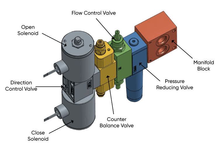
The above listed options will automatically lock pressure in the hydraulic cylinder to prevent position drift with no operator intervention required.
Manual Block Valves
The final option is to place a manual block valve (typically a ball valve or double block and bleed ball valve arrangement) between the HPU and the process valve's hydraulic cylinder which can be closed to lock pressure in the cylinder after valve operation.
HPU Flow Rate and Fast Valve Stroke Speeds
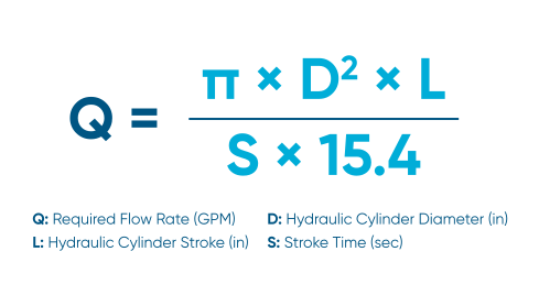
To achieve a specific stroke speed, the HPU flow rate must be determined. This can be calculated using the desired stroke speed and the size of the hydraulic cylinder being actuated (see Equation 1).
For example: A 10” bore hydraulic cylinder with a 20” travel (stroke) must close in 20 seconds. This translates to a required flow rate of 20.4 Gallons per Minute (GPM).
For example, if the cylinder requires 1,500 psi of hydraulic pressure to supply the necessary thrust required to actuate a process valve, then the required horsepower is 17.8 HP (see Equation 2). In this instance, the designer may select a 20 HP motor.
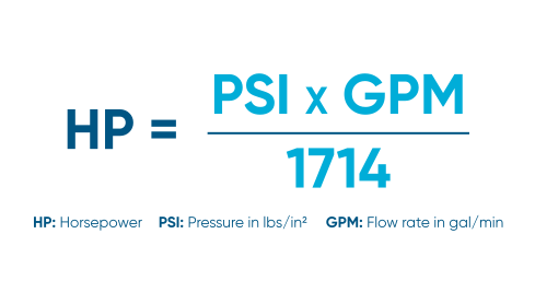
The relationship between hydraulic oil flow rate (i.e. valve stroke speed) and required horsepower is linear. If the valve is required to close in half the time, from 20 seconds to 10 seconds, the flow rate doubles. As a result, the required horsepower also approximately doubles, and the designer may select a 40 HP motor.
Using an Accumulator to Increase Valve Stroke Speed
Rather than increasing the motor size (which may require higher switch gear ratings, larger electrical cables, larger power supply, etc.), a hydraulic accumulator can be used to supplement the pump flow and meet the required valve stroke time. When the stroke operation is complete, the hydraulic pump will continue running to rebuild pressure and recharge the accumulator.
Accounting for Pressure Losses in Hydraulic Lines
In a practical application, dynamic losses through HPU piping, fittings, and field run lines that transport oil to-and-from the hydraulic cylinder must also be considered during the design process.
Depending on the length and diameter of the field lines, the additional pressure required to overcome these dynamic losses can be significant. This often requires collaboration between the HPU designer and plant engineer to balance hydraulic performance, system design, and overall cost.
HPU Controls: PLC, HMI and DCS Integration
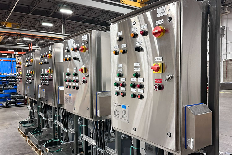
Stationary electric HPUs utilize a PLC based control system for operational flexibility and consistent system design. The HPU can be operated locally, using control components (pushbuttons, switches and LED indicator lamps), an LCD touch-screen HMI, or a combination of both. Local operator controls are located on the HPU electrical/control panel door.
The HPU can also be configured for remote monitoring and operation via the plant DCS or control system.
HPU Instrumentation and Monitoring
Hydraulic power units can be equipped with instrumentation to monitor pressure, oil level, temperature, and other operating conditions required for safe, autonomous operation.
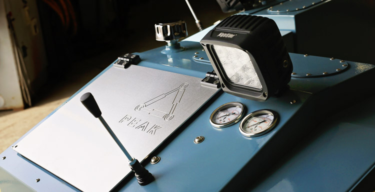
Portable HPUs typically use more basic instrumentation such as mechanical pressure gauges, electromechanical relays, and level or temperature switches. For example, a small gasoline powered HPU may only require one or two pressure gauges, whereas the more complex diesel portable HPUs require additional instrumentation including an alarm, an indication panel and a dedicated engine control panel.
Permanent HPUs with PLC based control systems are likely to be outfitted with more elaborate instrumentation, including analog transmitters, programmable devices, additional sensors, and a touchscreen HMI.
Depending on the HPU configuration and the optional features specified, the following is a list of instruments commonly used in an HPU:
Oil Tank Level
Gauge Glass(es) provide operators with a visual reference of the minimum and maximum safe operating tank levels, or 0 to 100% of the level transmitter (whichever is greater).
Level Switches (Float Type) provide discrete signals to the HPU PLC for the following conditions:
- High High: Hydraulic pump shutdown and High High Level Alarm
- High: High Level Alarm
- Low: Low Level Alarm
- Low Low: Hydraulic pump shutdown, oil heater lockout, and Low Low Level Alarm
Level Transmitters provide an analog level signal to the HPU PLC for level indication, alarms, pump shutdown, and oil heater lockout.
Oil Tank Temperature
Dial Thermometers provide visual indication for a local operator.
Temperature Transmitters provide an analog temperature signal to PLC for indication, pump shutdown, and alarm.
Temperature Switches provide discrete signals to the HPU PLC for the following conditions:
- High High: Hydraulic pump shutdown and High High Temperature Alarm
- High: High Temperature Alarm
- Low: Low Temperature Alarm
- Low Low: Hydraulic pump shutdown and Low Low Temperature Alarm
Hydraulic System Pressure
Mechanical Pressure Gauge(s) provide visual indication for a local operator.
Mechanical Pressure Switches provide discrete signals to the HPU PLC for the following conditions:
- High High: Hydraulic pump shutdown and High High Pressure Alarm
- High: Hydraulic pump control, OFF
- Low: Hydraulic pump control, ON
- Low Low: Hydraulic pump shutdown and Low Low Pressure Alarm
Programmable Pressure Switches (Dual Channel) provide discrete signals to the HPU PLC for indication, control, alarms, and pump shutdown. They can be used in place of mechanical pressure switches.
Pressure Transmitters provide an analog pressure signal to PLC for indication, control, alarms, and pump shutdown.
HPU Enclosure Temperature
Dial Thermometers provide operators with a local visual indication of oil temperature.
Thermostats (Heat / Cool) provide temperature control for HPU heating and ventilation equipment, if applicable.
Temperature Transmitters provide an analog temperature signal to PLC for indication, alarms, and control of HPU enclosure heating, ventilation fans, and motorized dampers.
Custom Hydraulic Power Units for Industrial Valve Applications
The right HPU configuration depends on more than the pressure required to operate a valve. Fail position, actuator size, stroke time, available power, control and instrumentation requirements, number of valves, and operating environment all influence the final assembly design.
PEAK Dynamic Systems designs and builds
custom hydraulic power units in Edmonton, Alberta for industrial valve applications throughout Western Canada. HPUs can be configured around specific process requirements, including fail-safe positioning, accumulator systems, fast stroke speeds, PLC/HMI controls, DCS integration, and instrumentation.
Contact our team to discuss the operating requirements for your hydraulic power unit.


