Hydraulic power unit testing verifies that a complete HPU meets its required pressure, flow, control, safety, and operating specifications before being installed in the field. Factory Acceptance Testing (FAT) can include functional testing, pressure and flow verification, accumulator testing, and low or high-temperature testing depending on the application.
Why Hydraulic Power Unit Testing Is Important
The performance of a complete hydraulic power unit is theoretical until it has been put to the test. While hydraulic pump manufacturers publish performance data and may test individual pumps before shipment, integrating the pump with piping, fittings, valves, controls, and other components can affect the performance of the final package.
Because an HPU combines components from multiple manufacturers, testing the complete system under temperature extremes can help confirm reliable operation before it is put into service.
What Is Factory Acceptance Testing for an HPU?
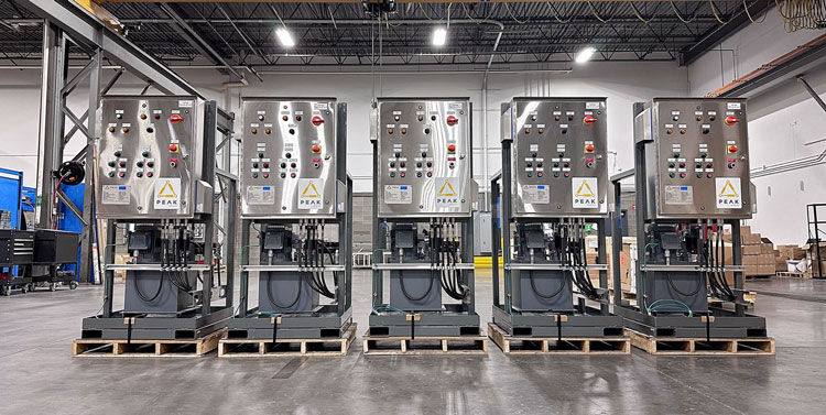
FAT is a final inspection and performance test completed before a hydraulic power unit is shipped to the customer. During FAT, the HPU is operated under controlled conditions to confirm that the hydraulic system, electrical components, controls, instrumentation, alarms, and safety functions perform according to the design specifications.
Pressure Relief Valve Testing
The pressure relief valve is an essential
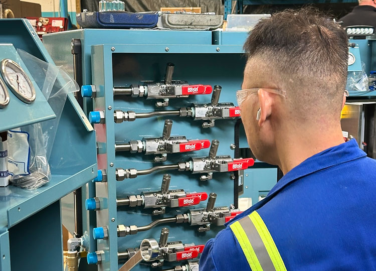
safety component in any HPU system. During FAT, the HPU is filled with oil, and the pump is operated with the pressure relief valve set to its lowest setting. As the pump builds pressure, the valve will bypass oil directly back to the tank, confirming that it is functioning correctly.
The operator will then adjust the pressure relief valve, increasing its setpoint until the desired maximum operating pressure is reached. A pressure gauge on the HPU pressure line will help the operator adjust to the correct pressure. Generally, the main pressure relief valve is set to 3000 psi, and any pressure generated in excess of this will be relieved back to the hydraulic tank.
Hydraulic Accumulator Bleed-Down Testing
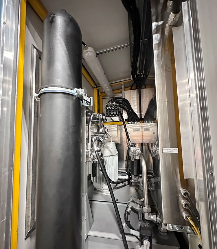
Whether used to provide hydraulic pressure for valve fail open/ closed, or to supplement pump flow, it is important to ensure hydraulic accumulator(s), and auxiliary connections are able to hold with minimal bleed-down.
Excessive pressure loss can cause unnecessary pump cycling on/off to maintain accumulator pressure. This will accelerate pump wear, oil degradation, and result in increased power consumption. This may reduce the stored hydraulic energy available during a fail scenario, possibly preventing the hydraulically operated valve(s) from reaching intended fail position.
A bleed-down test can be used to confirm each hydraulic accumulator's ability to hold pressure. The accumulator is charged to the desired pressure, monitored and limited by the HPU control system. When the design pressure is reached, the pump switches off, and the accumulator and related systems are isolated. Pressure is then monitored over time to ensure the system is fit for the application.
Verifying Pressure and Flow Performance
The pressure vs. flow curve of a hydraulic pump is published by the manufacturer and used during pump selection in the HPU design phase. Once the pump is integrated into a complete HPU, fittings, piping, directional control valves, hydraulic connections, and other components can introduce pressure losses that may affect overall system performance.
These pressure losses must be accounted for during the HPU design phase, but performance testing of the completed assembly is still required to verify that the system delivers the intended pressure and flow.
Performance testing confirms that the HPU can deliver the pressure and flow required for the application. Once installed at site, the HPU must provide enough hydraulic power to move the valve through its full stroke within the specified time.
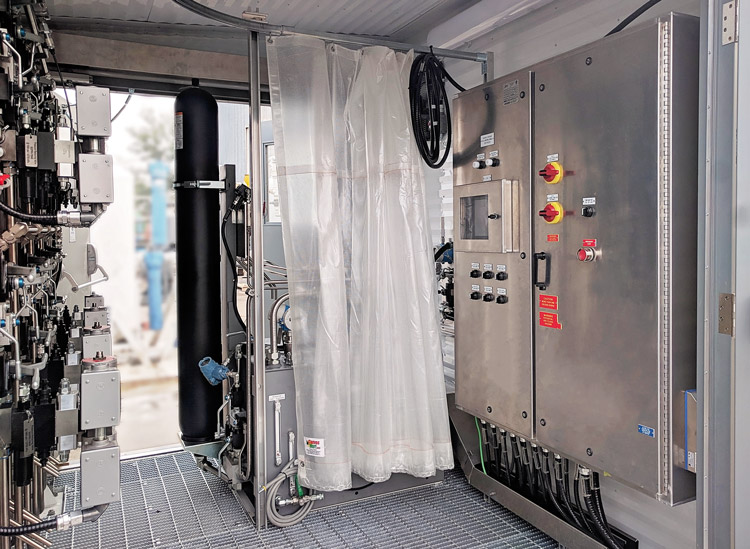
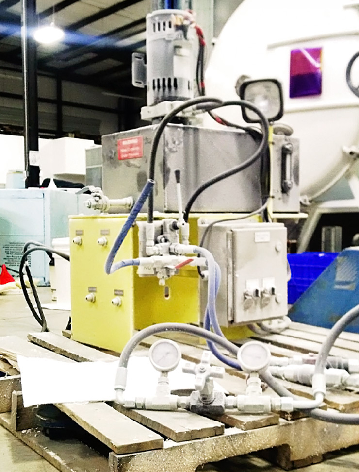
Proper performance testing in a shop setting will simulate these conditions for an HPU. Expected pressure loads, including actuator pressure and losses through field tubing and fittings are simulated using adjustable needle valves connected to the HPU output lines.
Flow rate at the required pressure is measured using a volumetric method or flow meter and compared against the design flow rate. Each hydraulic output is tested, whether the HPU is designed to operate one valve or multiple valves, to verify proper flow and identify any mechanical restrictions or blockages.
Completing this testing before shipment helps confirm that the HPU will perform as intended and reduces the risk of issues during commissioning.
Low-Temperature HPU Testing for Cold-Weather Operation
For hydraulic power units operating outdoors in Alberta and Western Canada,
low-temperature performance can be a critical design consideration. A complete HPU contains components from multiple manufacturers that have been selected and integrated by the HPU designer. While each component will typically have an associated temperature rating, it is important to verify functionality and suitability of the complete unit at the desired low temperature.
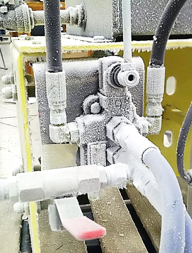
The HPU is placed in an environmental chamber and performance tested at the specified low temperature. Special attention is paid to the reliability and operation of moving components such as the pump, heater, directional control levers, switches and buttons. Hydraulic flow and pressure are measured to confirm that the selected low-temperature oil performs as required.
Electric motor power draw is also measured to ensure the field supply will be adequate to operate the HPU under cold conditions.
Cold-weather testing should evaluate not only hydraulic performance, but also how easily the HPU can be operated under actual field conditions. In addition to performance testing, the HPU is also reviewed for operator usability:
- How do the hydraulic hoses bend at low temperatures?
- Can they be easily manipulated and connected as required?
- Are operator contact points (levers, switches) easily operable with a gloved hand?
High-Temperature Control Panel Testing
Designing an HPU for high ambient temperatures is an important consideration. Many HPUs operate in warm environments, such as plant buildings, outdoors with direct solar exposure, or within heated enclosures during winter. The HPU also generates heat during operation, which can further increase internal temperatures.
This is especially important for the electrical control panel, which contains sensitive components that can be damaged or experience premature failure when exposed to excessive heat. Proper control panel design can help mitigate heat buildup through component placement, adequate panel sizing, air circulation, ventilation, and the relocation of major heat-generating components where appropriate.
An important consideration for outdoor summer operation is solar radiation. On a clear summer day, a south facing electrical panel with no shade can easily gain ~20°C internal temperature. Avoiding direct sun exposure and/or ensuring an electrical panel has a sun-shade is critical.
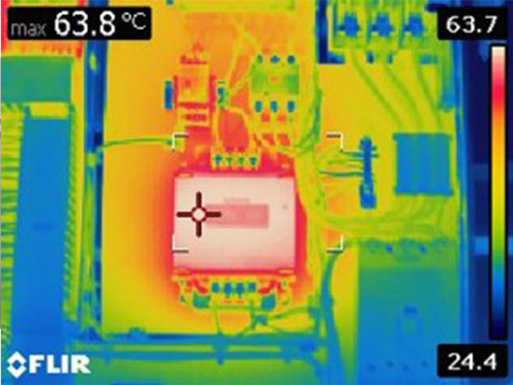
High-temperature testing can simulate expected heat gain from solar radiation and heat generated by internal electrical components. Strategically placed Resistance Temperature Detectors (RTD) can be temporarily installed to monitor and record temperatures in various locations internal and external to the panel.
Once testing is complete, the temperature data can be reviewed to evaluate the effect of internal heat generating components and direct solar exposure. If needed, mitigation strategies can be discussed with the end user such as an alternate location, orientation or use of sun-shade(s).
HPU Control Panel Cooling Methods
Filter Fans & Ventilation Louvers
Fans draw ambient air into the control panel and circulate it through the enclosure, while a discharge louver allows warmer air to escape. Incoming air is filtered to prevent excess dust or debris from entering the panel. Filter fans require ongoing maintenance, as the filters must be periodically replaced. Louvers must be covered during winter so the panel can retain heat.
Vortex Coolers
A Vortex cooler uses compressed air, which is readily available at most plant sites, to produce cold air that can be directed into the control panel to reduce heat build-up. Much like an air conditioning system, a vortex cooler also produces hot exhaust which must be re-directed. Excess air consumption may be a consideration when selecting this technology, as it will draw from the plant's existing compressed air systems.
Panel Air Conditioning
Small air conditioning units are available for cooling industrial control panels. One consideration is the space required for installation, as a panel air conditioner can occupy a significant area and may require a larger enclosure, or additional clearance around the panel.
HPU Testing Before Commissioning
Testing a complete hydraulic power unit before shipment helps verify that the assembled system meets its required pressure, flow, control, safety, and environmental performance requirements before installation on site.
PEAK Dynamic Systems designs, builds, and tests hydraulic power units in Edmonton, Alberta for industrial valve applications across Western Canada. Depending on the project requirements, testing can include FAT, pressure and flow verification, accumulator testing, functional testing, and low/high temperature performance testing.
Contact our team today to discuss your HPU requirements.